Model Build Process
The j2 Universal Tool-Kit provides many ways that models can be developed with speed and ease. However, j2 Aircraft Dynamics Ltd. like to go one step further. As well as providing the tools, we provide a fully developed process to support your engineering activity.
The process can be tailored to an organisations existing capability tools and techniques to maximise Return on Investment. This can be developed alongside the Knowledge Transfer activity.
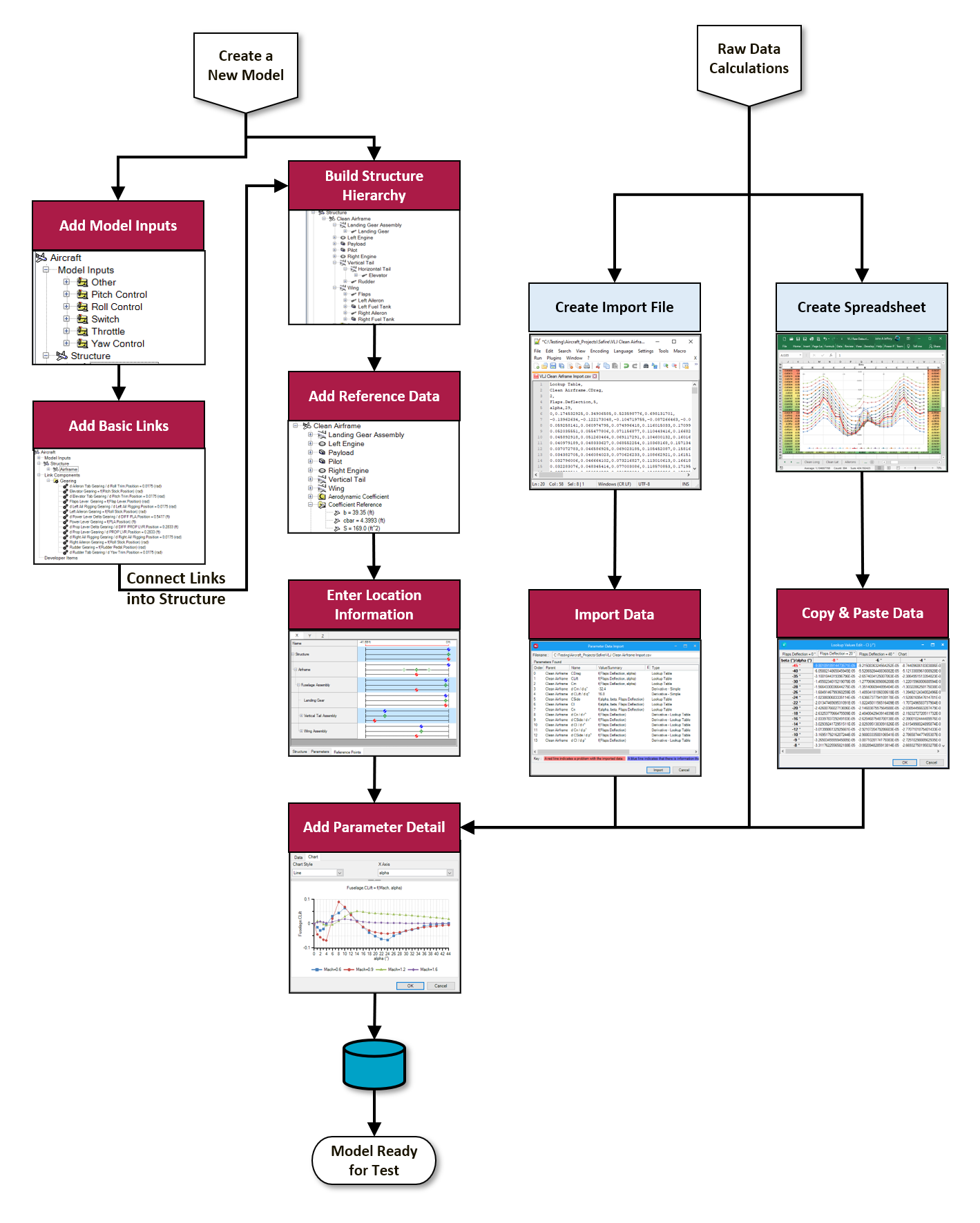
An example of model build process is described here:
 Create a New Aircraft Model
Aircraft Model Projects can cover any type and class of aircraft, from fixed-wing and rotary-wing. Models are automatically version-controlled and can be organised under different projects or categories.
- Create Model Structure
Build up the model information from the available Structural Items to create assemblies and sub-assemblies, to replicate the aircraft configuration and layout. Items can be moved and re-located later if the configuration changes, without having to re-build the complete model. When relocating or renaming items, links and connections are automatically updated and tracked to ensure that items are not lost.
- Add Model Inputs
Model inputs provide a means of getting information into the model from outside, including pilot inputs, failures or alerts, configuration data and payload.
- Add Simple Gearing Links
Start with simple gearing to scale inputs into deflections and dynamic item characteristics. Additional Links for actuators and FCS components can be added later as the model fidelity is updated.
- Connect Links to join Model Inputs to Dynamic Structural Items.
Once the Links are in, the inputs for dynamic items are connected to the outputs from the Links to allow them to be “driven” where necessary. Unit Types are checked between deflections and Link Outputs such that they are consistent.
- Add key reference information on model
This information includes the Area, Span and Chord of the main wing and airframe reference data. Individual Aerodynamic Items can each have their own Reference Data if required to enable them to be scaled when necessary.
- Locate Structural items
The location of items where their aerodynamics are acting, and any cg information when there is mass and inertia, is very important. This enables the software to automatically calculate the influence of different Structural Items on the overall behaviour of the aircraft. Moving an item or its parent means that the whole sub-assembly is moved without having to re-enter all the information.
- Reference Location is relative to Parent’s Reference Location
- NP and CG are relative to Reference Location
- Engine Centre of Thrust Relative to Engine Reference Location
- Prepare Raw Data
Where is the data coming from? It is worth collating all the various sources of original data so that these can be referred back to. Depending upon how the data is to be entered onto the model, this can be stored in:
- Text/Import File
- Spreadsheets
The aim is to make model building as quick as possible. Users can copy tables straight from the spreadsheet or text file and paste them straight onto the model, avoiding any retyping errors. If data is formatted into an import file, it can be imported and automatically associated with the various Structural Items on the model.
- Import Parameters
- Copy and Paste from Spreadsheet
- Type directly into Properties
- Save
The model can be stored in the database and is accessible to all team members for subsequent analysis.
- Test the Model
Once it is completed and inspected, it is worth running a series of checks to identify any errors.