Hierarchical Model Structure
When developing an aircraft model, many factors contribute to the aircraft’s behaviour, including aerodynamics, mass and inertia distribution and propulsion systems (jets, propellers, helicopter rotors, multi-copter rotors etc.). When using flat files or developing code, these factors can be extremely difficult to keep track of, while their interrelationships may vary depending upon their relative locations. All this can result in a complex model development process that is prone to error and becomes even more complicated when modifications or variations are considered.
The j2 Universal Tool-Kit allows engineers to create their models in a graphical environment with a hierarchical structure. This structure can mimic the aircraft’s layout of structural assemblies and sub-assemblies.
That means the model is much easier to navigate, with a recognisable layout mirroring that of the aircraft. Data is added to the Structural Items list, providing a clear picture of the aircraft that automatically processes individual variables.
1
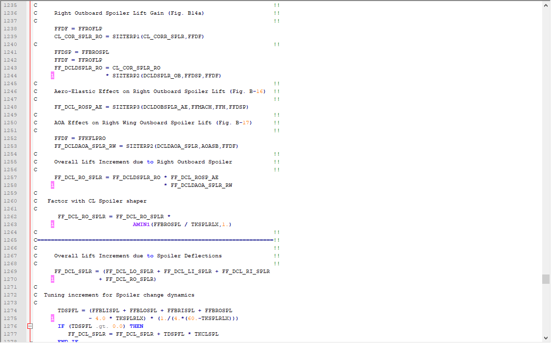
Traditional Code
The traditional way of developing models through requires all interactions and contributions to be assembled and manually coded. To calculate the total contribution for lift alone takes 1500 lines of code.
2
Block Diagram
Even when working with components in block diagrams, each interactions needs to be assembled and the total contributions put together to create a whole aircraft. These then need adding to the equations of motion and the full system created. This can take months.

3
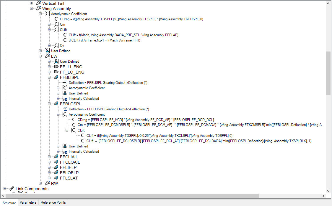
Hierarchical Model
When putting the model together in j2 Builder, the hierarchy enables the model to reflect the aircraft. Each entity can be added and its contribution to the aerodynamics defined. j2 Builder then assembles all the contributions to provide the total value.
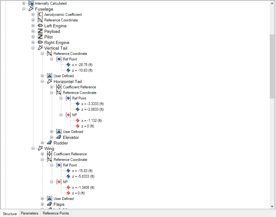 Each item in the hierarchy is assigned its own reference location, made up from the various Parameter Types relative to the parent. This means that when the parent’s information is changed, the attached child item is moved automatically.
So, when designing an aircraft and investigating configurations, all relative distances are automatically managed, removing the possibility of items being left in the wrong location. This is a distinct improvement in work process and greatly reduces the need for re-work.
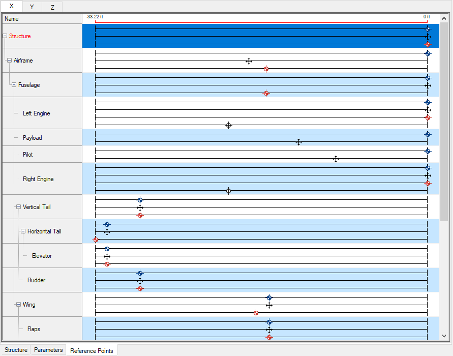
The reference map provides a visual representation of the relative and absolute locations of all items for further checking.
 As the hierarchy includes the locations of items, these locations are used to calculate the corresponding moments from the forces. This avoids the need to add extra equations, as all moments relating to a chosen reference location are calculated automatically.
Each item in the hierarchy can also have its own mass and inertia information and centre of gravity. The total values for the aircraft are automatically re-calculated at each step – including time-dependent values such as fuel burn or load drops.
Once again, this saves time over coding a solution, where moment arms and individual contributions all need to be totaled manually. If there is a change in the configuration or an item is moved, the software will automatically re-calculate all aircraft values instantly.
For further information on what j2 Builder can offer, see: