Rotary Wing Characteristics
Dynamic Pressure Loss
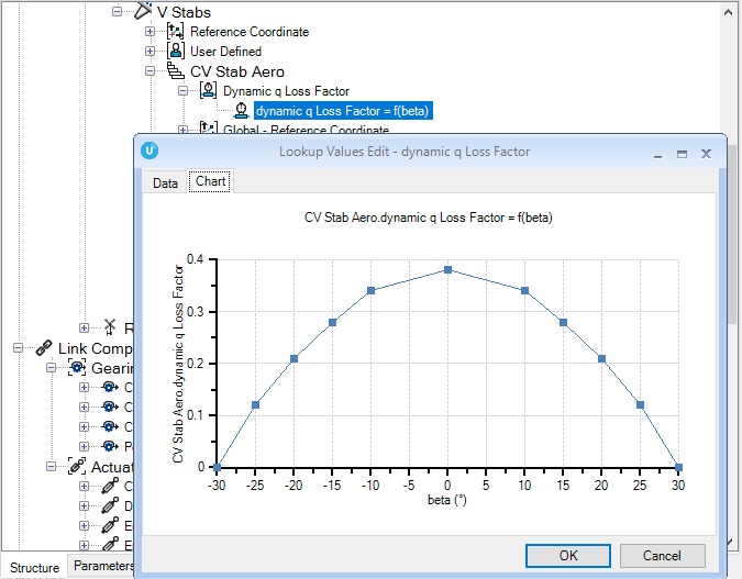
 When dealing with rotary wing aircraft, Rotor downwash, rotor hub and fuselage wakes combine to disturb the air mass impinging on the tail, directing the flow downwards and to the side of the tail fin. At the same time, there is a dynamic pressure loss which reduces the efficiency of the aerodynamic surfaces. A peak pressure loss of 50 % is common. Furthermore, the position of the pressure loss is dependent on the trimmed flight state. At lower forward speeds the region of pressure loss passes below the tail. At higher cruise speeds there is the maximum effect on the tail rotor and vertical surfaces, and, as speed is further increased, cleaner air once again returns to the tail. In global terms, an efficiency factor can be included in the theoretical calculations to account for the phenomenon. In the worst case, the factor reaches around 70 % efficiency of the theoretical value for the tail under ideal conditions.
The problem of dynamic pressure loss is inherent with all tail configurations. A high or low design may have particular advantages · at one trimmed flight state but to the detriment of another.
When developing rotary wing aircraft, j2 Elements allows for a dynamic pressure loss factor to be added into the lifting surfaces (empennage).
Velocity Contributions at the Tail Surface Locations

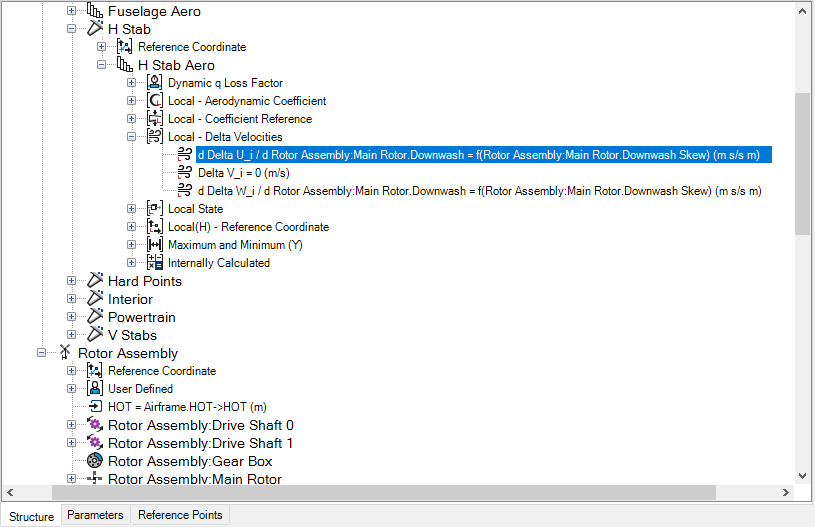
Helicopter investigations have shown a swirl of the wake behind the fuselage with substantial amounts of sideward velocity components. And naturally the rotor downwash and wake deflects the airflow at tail locations downwards but not symmetric to the vertical plane. This is due to the fact that the main rotor loading varies from left to the right side. This results in additional velocities on the empennage.
Again the j2 Elements plug-in provides the ability to add the wake effect velocities from the main rotor.
For more information see:
- j2 Elements
- Aerodynamic Strip Theory
- Horizontal and Vertical Strips
- Rotary Wing Characteristics
- Downwash